ConnectBox Getting Started
Model P – Battery Operated
Model S – Line Powered Only
Model P1 V6 Model S1 V6
P/N 10001 P/N 10002

Model P2 V7 Model S2 V7
P/N 10011 P/N 10012
Download Current Document:
Connectbox V7 hardware Getting Started, V2.x firmware
Download older Documents:
Connectbox V6 hardware (with power side switch), V1.X firmware
Getting Started simplified V6 hardware, 1.x Firmware
Contents Of this Document:
1. Overview and Initial Connection
2. Nano Pi Neo 2
3. Raspberry Pi
4. Orange Pi
5. Differences between Model P V6 and Model P2 V7 as well as Model S V6 and Model S2 V7. 2
6. Initial Setup
7. Connecting to your Device
8. Adding in Media Content
9. Using the Chat functionality
10. LEDs and Screen Usage
11. The Administrator Web Page
12. Configuring your unit
13. Enabling SSH for the device
14. Upgrading the firmware with interim patches
15. Enabling Custom Web Interface
16. Enabling Custom WordPress installation.
17. Linking your Connectbox to Control Host
18. Features
1. Overview and Initial Connection:
This ConnectBox is nearly ready to go, just a few things that you need to do first to make the end user experience useful.
Units shipped after May 1st, 2022 or units retrofitted with firmware version 2.0 will use this Document. If your unit is older or has **Version 1.X** firmware please refer to the **ConnectBox- Getting Started_V6** document. If you would like to update to the latest firmware you may do so by downloading and burning the firmware onto a

to

speed uSD card. It is important to ensure that the uSD card you use is of good quality and has the proper speed markings. The location to download the firmware is https://Github.com/ConnectBox/connectbox-pi/releases and you are looking for the latest NEO Connectbox image. This can be burned on the uSD card using a tool Balena Etcher on either a Windows machine or Macintosh machine or Linux machine. See the ConnectBox Upgrading your firmware for hardware version V1-V3 or V4-V7 document on the Connectbox.org website.
The platforms that are supported by version 2.0 and latter firmware with additional hardware are:
2. Nano Pi Neo Systems:
as shown in Model P, P2 and Model S, S2 above
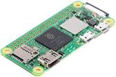
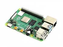
3. Raspberry Pi Systems:
Raspberry Pi Zero W:
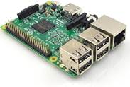
Raspberry Pi 3+
Raspberry Pi 4
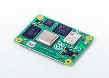
Raspberry Pi CM4:
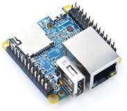
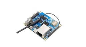
4. Orange Pi Systems:
Orange Pi Zero2:
5. Differences between Model P/S V6 and Model P/S2 V7 as well
The main difference between the Model P V6 and Model S V6 vs the Model P2 V7 and Model S2 V7 is that there is an additional Wi-Fi module incorporated internally for connection to the internet via a Wi-Fi (or via tethering to a mobile phone.) Additionally, the Model P2 and Model S2 have OTG capability on the USB C power port allowing you to connect it directly to a host computer to enable data transfer to other client hardware. Also, we have upgraded the firmware from V1 to V2 allowing a more visually appealing user experience. We have also added language detection of the client and support multilingual content based on ISO code identified folders in the data section. We have added phone home capabilities to allow a central control server to manage multiple Connectboxe’s in the field receiving statistical data on usage, allowing control over all configuration features, and uploading of new content to each unique Connectbox based on location.
Another difference between a V6 hardware and V7 hardware is that V6 has a slide power switch on the side where V7 has a push for 3 second turn on and push for 6 second turn off mode on the 1st switch closest to the LCD display. The V6 switch when turned off will keep the power up on the unit for about 20 seconds before going down to allow the system to save its state. However, when you switch a unit off it will immediately stop transmission over the Wi-Fi. The V6 hardware uses micro-USB whereas the V7 hardware uses USB-C connector as the power/communication port
6. Initial Setup:
- 1. ConnectBox comes with internal system software. No content is included other than a readme file. You’ll need to add your own content to the device using the guidelines in the sections below.
- 2. Your battery version ConnectBox comes with an internal lithium-ion battery which is shipped at 30% charge level. To charge the battery, you will need to connect it to a 1A (2A for Version with Raspberry Pi) or greater micro-USB/USB-C charger like are found with many cell phones. For charging from an empty to full battery, expect it to take around 4-15 hours the first time ans 4-7 hours subsequently. Your ConnectBox has built-in low battery protection which prevents the battery from going into deep discharge as well as from overcharging.
PLEASE FULLY CHARGE YOUR CONNECTBOX BEFORE THE FIRST USE
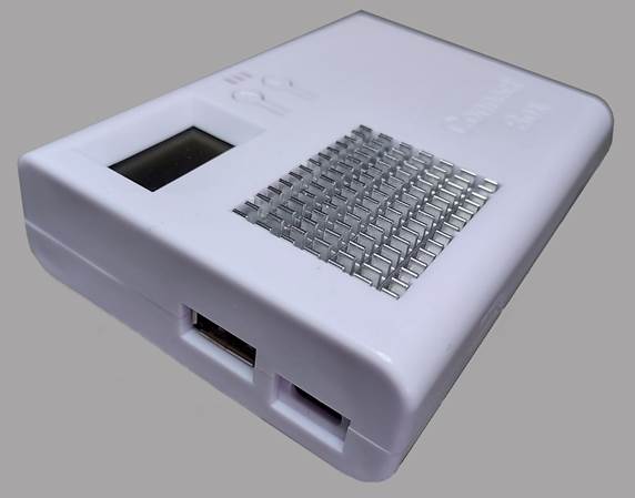
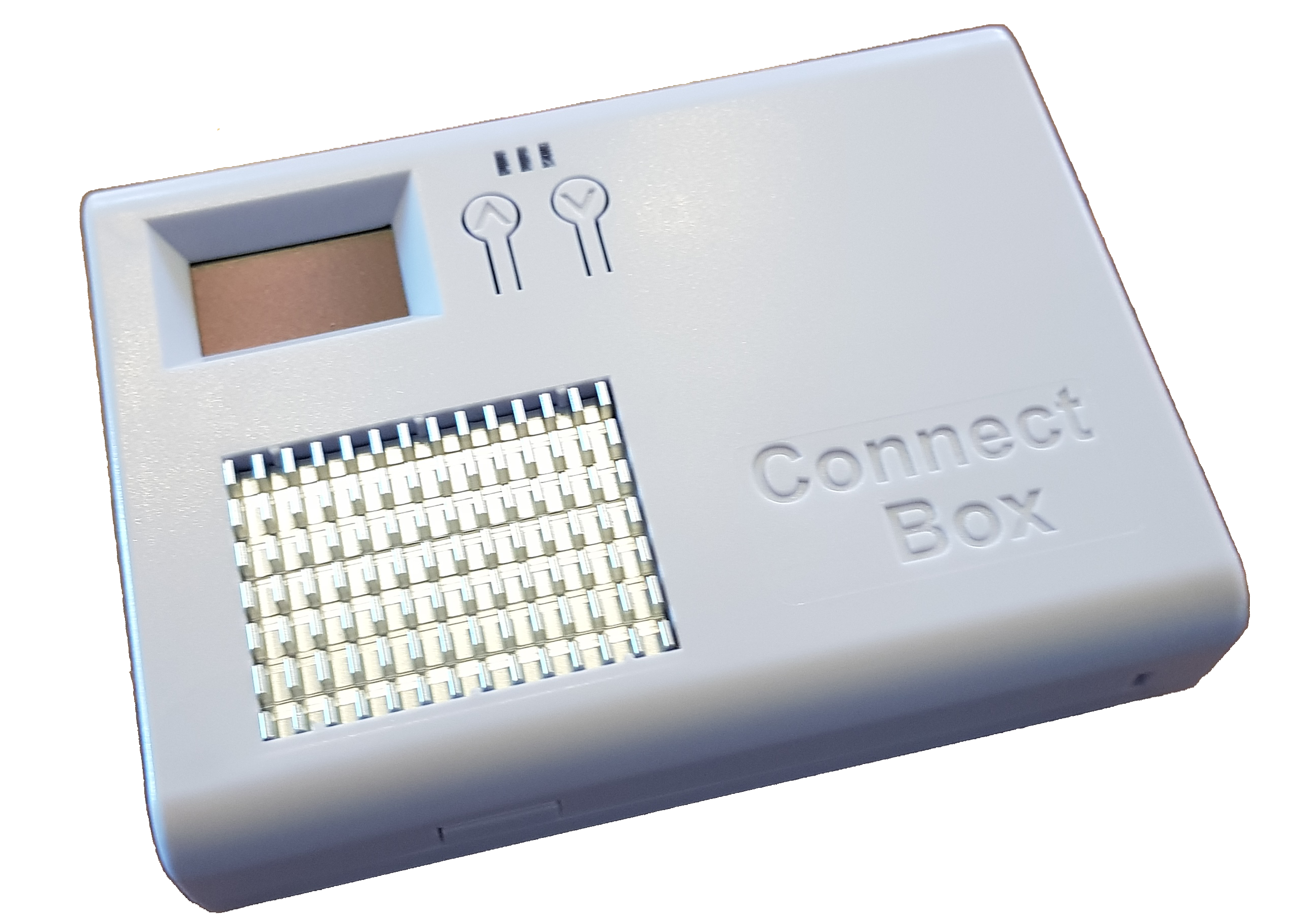
Connectbox Model P2 V7
press for 3 seconds to turn on / press for 8-10 seconds to initiate a power down cycle which will take 30 seconds. However, as soon as the amber LED goes out it will stop transmitting.
- 3. With the micro-USB/USB-C charger plugged in or with a relatively full battery, turn your unit on using the switch on the side of the unit or pressing the power on button for 3 seconds.. Allow a up to 5 minutes on the first power up, and subsequently a minute or two to pass before using a wireless device to locate and join the default wireless network with the default called:
ConnectBox – Free Media !
You will know when it is available by the **orange** LED turning on. (Note: that if you charge your unit and run the unit simultaneously in a hot climate it may cause a red flashing indicator of high temperature internal to the unit.) Units version 3 – 6 of the connectbox have an on/off switch. Unit version 7 forward of the connectbox do not have an on/off switch. Instead hold the ˄ up arrow key for 3 seconds to turn on and hold the ˄up arrow key for 8-10 seconds to initiate a shutdown and turn off of the device.
7. Connecting to your Device:
After the unit is on and you see the **Orange** LED indicating that the Wi-Fi hotspot is transmitting, using your mobile phone, or tablet/laptop open the Wi-Fi settings menus and look for Connectbox Free Wifi ! Select that Wi-Fi connection and your device will connect and then direct you to the captive portal to validate connectivity to the Connectbox device or check if a login is required for the network join. In this case it will show a web browser window that say’s to connect to
http://gowifi.org
In some cases you may need to go to the more menu (sometimes three vertical dots ( ⁝ ) and keep the connection. On the captive portal page, you will be asked to enter http://gowifi in the URL window. This should open the default front page of the Connectbox. (Note: on some Samsung Galaxy phones or newer mobile phones you may be directed to turn off your cellular data for the Wi-Fi to fully work. http://gowifi.org will tell you if you need to do so. If so, turn off your cellular data connection as your phone will default to using that for internet rather than the connectbox. Once you turn off data, pull down on the screen and it will refresh returning you to http://connectbox.org or the appropriate hostname of the device. If you know that your phone will connect easily you can use http://wi.fi as a shortcut to opening the front page menu.
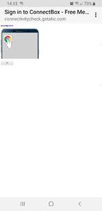
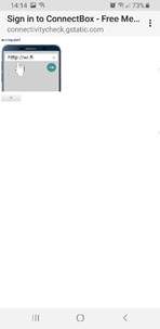
When you re ready click OK. or use the highlighted hot web link on the top of the phone image to connect you to the ConnectBox. This is needed to make the connection and then you will be redirected back to the Wi-Fi connection page. If not, please close this browser. Once connected, you will need to open up a browser on your device (native browser, chrome, safari, Firefox, etc.) and type in the web address of [http://gowifi.org](http://gowifi.org) which will then result in seeing the main ConnectBox window, or again if the cellular data is an issue will instruct you to turn that off. It will show a blank screen as:
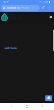
Although the default settings for the ConnectBox make it usable without any changes, data needs to be added for the users to view. Additionally, the Configuration options (discussed below) are available for those who wish to customize the operation of the ConnectBox.
8. Adding in Media Content:
You have the option of connecting an external USB stick to the USB A port that is available on the ConnectBox’s exterior. The USB A port will in a sense override any content that is stored on the micro-SD card within the unit. The USB stick should be formatted for EXT2, EXT3, EXT4, FAT32 or NTFS format. We recommend a slim line USB media stick like the SanDisk Ultra Fit line for low profile and USB
speed is recommended for faster system operation. Disc capacities from 4 GB up to 512GB can be used. Media content can be added to it using a Windows or Mac system. Folders can be used at your choosing and the file naming conventions can utilize the full character set of UTF-8, meaning non-roman scripts can be used.
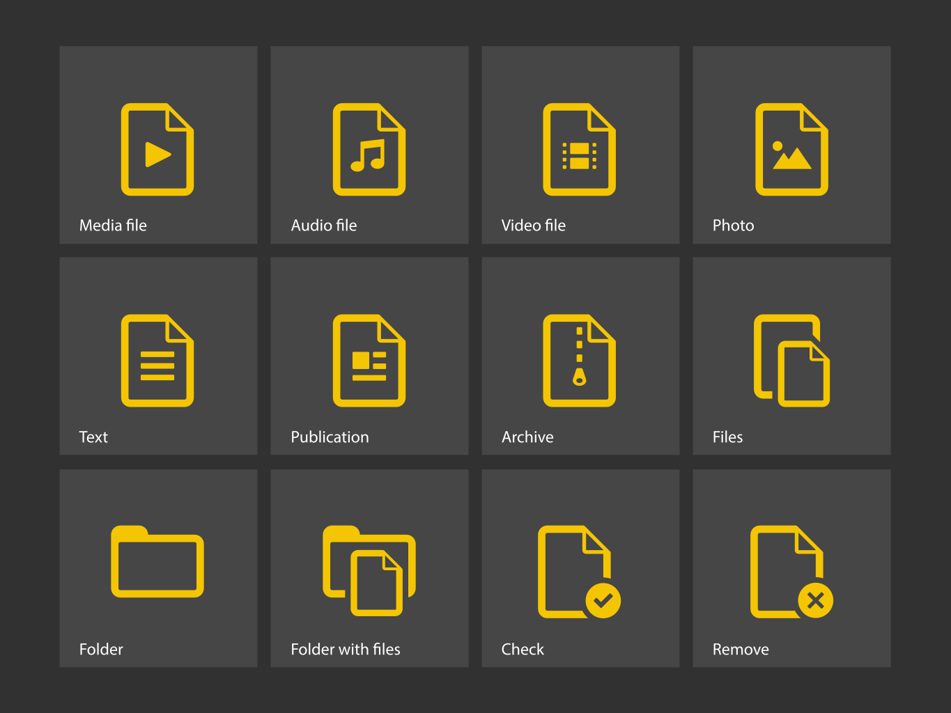
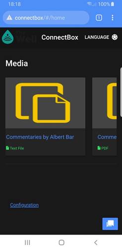
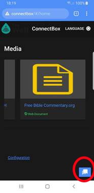
The unit will default to an enhanced user interface. This interface creates thumbnails of media content at the root level/content folder and icons of folders for specific media contents. The icons look like this:
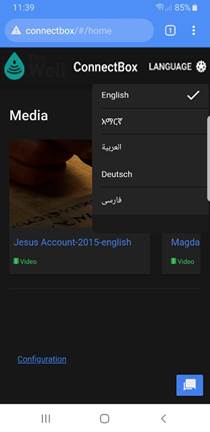
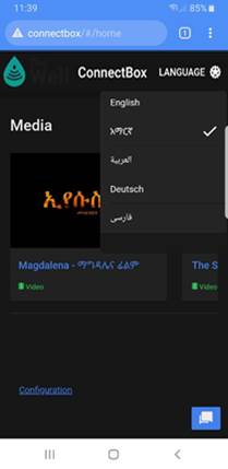
Additionally for language support, create a folder at the content level with the ISO code of that language according to the ISO 639-2 which consists of 2 characters or 3 characters representing the language code. When a folder at the content level has a language code it will be hidden from the default language and listed in the language listing of the device. When a user with a mobile phone/tablet/computer connects to the connectbox with that language set by default in the operating system it will automatically load that language folder page as the root display. Users can always select the language they would like from the drop-down language listing:
This example would have a folders labeled:
root directory: ── content
├── en
├── am
├── ar
├── de
└── fa
Folders at the content directory that do not contain valid ISO language codes will be ignored. There also should be no media at the content level if language folders are used as it will be ignored.
If no language folders are used then the entire contents of the USB flash drive will be considered without a selectable language. Any folders at the content level will be displayed using the default icons above with the appropriate media contents listed and any media in the content folder will be displayed as appropriate.
Note: media that is at the root level or other files at the root level are ignored by the ConnectBox unless specifically used for administrative purposes. See Enabling SSH and Upgrading firmware for these cases..
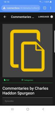
Media contents are scrolled starting from right to left meaning swiping left on your phone screen will reveal additional media if available. Media that is a collection of contents will be supported under a file structure. When you enter that structure it will list the other items available. This includes audio files that are sequenced in episodes for sequential listening, chapters of books, etc. Within a media folder multiple types of media can exist. This means you can have video content along with study guides, and audio content.
Media type supported are: mp4, pdf, png, jpeg, mp3 apng, avif, gif, svg+xml, webp, webm, ogg, etc. See the detailed support documentation on browsers to get an understanding of the containers vs the codecs used in different media types.

For elements of a collection:
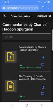
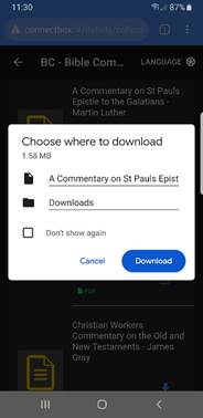
Selection of the folder then provides a view of the content scroling up, showing the different types of content and either a view button or a download button. Selecting the view button will either show the media and allow you to interact with it or, you can select the download button to store it on your current device to look at later. Note that in this exaple there is a zip file of the Commentaries by Charles Haddon Spurgeon as the first item in the folder. Where the second item is a pdf file that can be opened with the built in pdf reader or downloaded.

To move backwards from your current location either cancel, or use the upper left back arrow (sometimes you will find an upper right X to press to stop the media player then use the upper left back arrow. Additionally, you can always use the devise back arrow button on the bottom or swipe back in some cases. In the case the file contains HTML media and an index.html file exists it will open in your browser that media directly. Navigation in this case is dependent on the application and you can always go back to starting screen by typing in the browser address bar http://connectbox or whatever the name of your connected system is. If all else fails type http://gowifi.org in the address bar.
9. Using the Chat functionality:
Built into the main function of the Connectbox is the ability for users connected to the box to converse with one another. This is entered by tapping the chat icon on the bottom right of the screen:
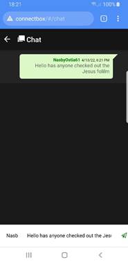
This opens the chat window:

Note that your name is automatically generated and is random on the bottom left input bar. You can change the name of the user in the bottom left panel and enter the text of the message in the bottom right panel. Once entered it is posted by pressing the right airplane button on the bottom right the message is posted in a group chat.
All users can see all messages that have been posted.
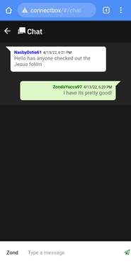
To exit the chat function simply press the back arrow on the top right of the screen.
Note: Chat history is only maintained while the unit is on. As soon as the unit is shutdown the chat history is deleted.
10. LEDs and Screen Usage:
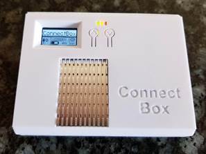
On the top front are three LED s as well as one display and two buttons. The Green LED indicates that the power is turned on. The Orange LED indicates that the system is booted and that Wi-Fi signal is transmitting. The Red LED is lit during battery charging and will be extinguished when the battery if fully charged. Additionally, the RED LED may blink to indicate a trickle charge is occurring with the battery when the battery voltage is under its desired minimum of 3.2V or when the battery is overheated.
NOTE all screens can be controlled by the local system administrator and can be enabled or disabled. Your experience and screen movement may vary from this guide due to some screens being turned off by the administrator.
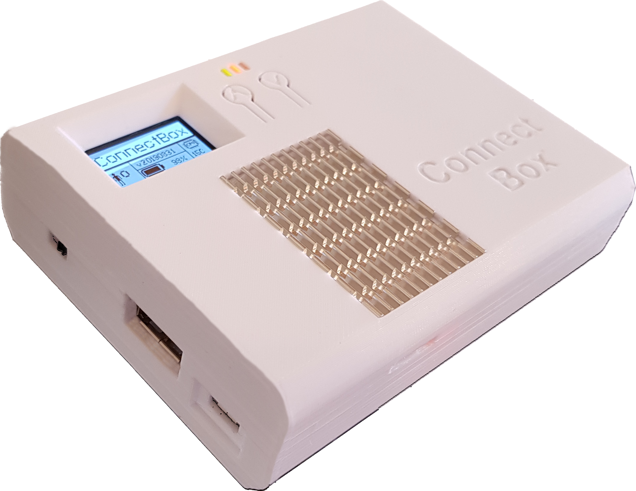
The OLED screen on power up will show the ConnectBox logo for a short period of time then turn off. The two buttons,

ressing the up_ button for 1 second will bring up the first status screen:
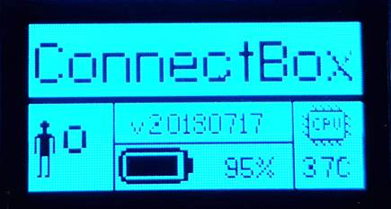
This screen shows the number of connected people, the version number of firmware in the unit, the battery charge level (Note: on a battery less ConnectBox this area is blank) and the CPU temperature. .
Pressing the up button again for 1 second with the first status screen on, will bring up the second status screen.
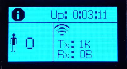
This screen shows the time duration that unit has been on, the number of people connected and the aggregate transmit and receive volume of data the unit has sent/received since powered on.
Pressing the up button again for 1 second with the second status screen on, will bring up the third status screen:
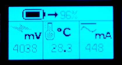
This screen shows more detailed information on the battery. This includes the current battery power level in %, the voltage of the battery, the temperature of the power control chip and the current in or out of the battery (as indicated by the directional arrow). Note that the battery is a 6400 mAh battery or a 6200 mAh battery depending on model. On a battery less unit the % area is blank and the mV area show the voltage input from the power module and current being drawn from the power module.
At any time after the first screen pressing the down button for 1 second will go back a screen.
Pressing the up button again for 1 second with the third status screen on, will bring up the fourth status screen:
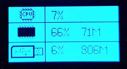
This screen shows the amount of CPU usage in %, the amount of RAM memory usage in % as well as the free memory and the amount of USB storage used in % and the amount of free space. Note: that is you are not using an external USB for storage this will show the available space on the internal uSD card for data.
Pressing the up button again for 1 second with the fourth screen on, will bring up the fifth status screen:
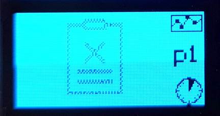
This screen shows the most popular downloaded or viewed files on the unit **over the last hour**. This screen show p1 indicating it is page one of the reports of hourly usage. Pushing the up button again to see page p2 . If there is an empty clipboard symbol, there are no statistics to view.
Pressing the up button again for 1 second with the Sixth screen up will show the Seventh screen indicating the most popular file activity for the last Day. The p number represents

This screen shows the most popular streamed/downloaded files on the unit for the day. If there is an empty clipboard symbol, there are no statistics to view. The p marker shows which page of the report (1 or 2) you are looking at.

Pressing the up button again for 1 second with the Eighth screen on, will bring up the Ninth status screen showing the most popular streamed/downloaded files on the unit for the Week. If there is an empty clipboard symbol, there are no statistics to view. The p marker shows which page of the report (1 or 2) you are looking at.

Pressing the up button again for 1 second with the Tenth screen on, will bring up the Eleventh status screen showing the most popular streamed/downloaded files on the unit for the Month. If there is an empty clipboard symbol, there are no statistics to view. The p marker shows which page of the report (1 or 2) you are looking at.

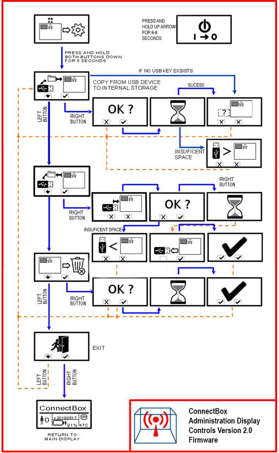
Pressing the up button again for 1 second with the 12th screen which is the Administrator management screen. From this screen you can enter into some of the unit media magsmen functions., However to do so requires you to press and hold both the up and down keys for at least 6 seconds while the management screen is shown. Once the up/down keys have been pressed for 6 seconds the screen will change to the media copy screen. From here you can navigate he administrative functions to copy from an external USB key to the internal uSD memory, copy from the internal uSD memory (media only) to a USB key, or you can delete all media on the internal uSD key.
If no buttons are pressed on any screen after 10 seconds, then the screen will go black again to conserve battery power. Pressing the Up button for more than 1 second will again show the first screen.
For the administrative functions use the following guide to show how to mange the copy to, copy from and delete functionality of the internal uSD storage space.
11. The Internal Administrator Web Page:
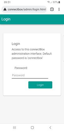
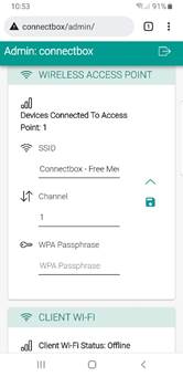
Navigate to the Administration area: [http://connectbox/admin](http://connectbox/admin) (or press the cog icon on the bottom right of the screen) and login with the default Connectbox credentials (username and password are case sensitive):
username: admin
password: connectbox
It Is A Strong Recommendation : That you change the password for the Administration area. Go to the Configuration Menu and select Password. Enter a new password and press submit. When you next try to enter the admin portal of the Connectbox, you will be prompted to login again. Use the new password when this happens.
12. Configuring your unit:
Configuration of your unit is done through the following pages:
Password:
Password allows you to change the system password for the Administrator functions (Note: we highly recommend changing the administrator password from the default connectbox ) Note that after setting these values you must press the disk icon to save the data.
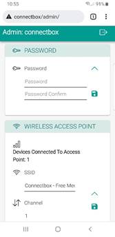
Wireless Access Point allows you to change SSID (wireless display name) and or select the WiFi channel and increase security by adding a WPA passphrase. Note: that in basic mode it only allows you to change the unit SSID. To change the Wi-Fi channel which is automatically set by scanning the area for available channels, or add a WPA passphrase for WPA2 security. You must enable the enhanced interface lower in the menu first before going to the Wireless Access Point menu. Note also that this screen will show the number of connected users. Note that after setting these values you must press the disk icon to save the data.
WiFi Channel:
Change the Wi-Fi channel to something that might be less congested in your area. (Configure -> Channel) Your choices are channels 1 11 or 1 14 depending on the country. It is a suggestion to the media box as it will scan all available channels in your area based on the country you re in (from the Client Wi-Fi country setting) and if appropriate will give you the selected channel or if another one is better it will select that one.. When you change the Wi-Fi channel, you will temporarily be disconnected form the Connectbox until your device reconnects to the Wi-Fi SSID on the new channel. Note that after setting these values you must press the disk icon to save the data.
WPA Passphrase:
Setting a WPA passphrase will force any user wanting to connect to your Connectbox to have a password to connect. This is appropriate in places where you want to control who connects. The Passphrase needs to be something easy to remember and should be reasonably long such as a phrase without spaces, but may contain numbers and other characters. Using good practices for creating a password is the same as creating a good Passphrase. Note that after setting these values you must press the disk icon to save the data.
Client Wi-FI:
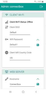
Allows you to scan and set the SSID of the access point you want to connect to internet for this device., The Wi-Fi password needed and the country code where your located to manage the channels it will look at. Note that after setting these values you must press the disk icon to save the data. Setting the client configuration will be held and when the device in in range of this Wi-Fi signal it will connect. After setting you can pull down on the screen generally to refresh it and if it is connected it will indicate Online. If there is no Wi-Fi signal available or the SSID/Password are invalid it will show Offline.
Device Hostname:
Change the name of the hostname (by default this is connectbox ) to something of your own choosing. From the admin menu, go to (WEB SERVER: Hostname). This appears in the location bar of the browser. If you are changing the hostname, you will need to use the new http://hostname for the default web page, or http://hostname/admin for the administrative area. Additionally, after the change, you will have to login again as your credentials were for the last host. After changing the hostname press the disk icon to save it and make the change permanent. This hostname is also what is broadcast to the client side and will be visible when connected via Wi-Fi client.
Uplink Via Mobile Phone:
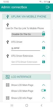
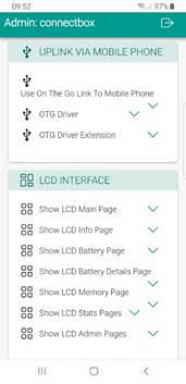
This section allows you to configure the OTG (On the Go) functionality of the device (V7 devices only). This includes allowing the USB C port to be used as a serial port to your host computer (serial ssh into the device), or if your device will look like a hard drive to your host system, etc. Please refer to the advanced administrative guide for further information. NOTE: changing values in these fields have a direct impact on how the device functions and may cause the device to become inoperable to the Host. Only change these options when you fully understand what you are doing and when you understand the implications of what you are doing. Note that not all of the setting paramaters are visible unless you have enabled the advanced configuration setting on the admin menu.
LCD Interface:
This section allows you to configure what menu options are available on the front panel of the device. Each page of the device can be turned on or off depending on the values set. Note: when you set Show LCD Admin Pages to off , then all administrative pages are disabled. You muse enable advanced configuration in the administrator pages to see this option
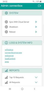
System:
Sync With Cloud Server:
The system menu items allow you to force a Sync with the Cloud based host package server. This will sync your statistical information as well as pull down any additional configuration items setup by the organization. This operation will occur naturally if the device is connected to the Internet providing Wi-Fi hotspot configured in the Client WiFi. or by tethering your unit to your mobile phone through the USB C connection. Not that this is only available if you have setup the cloud server data in the server section of the administrative menu and there is a hosted cloud server that is available. Internet connectivity is required to use this function.
The shutdown button allows you to quickly shut the system down if individuals are looking for the device remotely. It will then power off as well.
Shutting Down the Unit:
Will shut down the ConnectBox remotely Note V1-6 units: power is still on, but all functions will stop and the Wi-Fi signal will stop immediatly. To reduce battery, drain, turn the power switch off. Note V7 – units: Power will be shut down after 30 seconds but the Wi-Fi signal will stop transmitting immediately. (This can be used in creative access countries to quickly shut the unit down without having to touch the unit)
Rebooting the Unit:
Will shut down and restart the ConnectBox Note: it will take 30 – 240 seconds before the Wi-Fi signal comes back again. This forces all attached devices to disconnect and then have to reconnect to use the ConnectBox. It wipes the chat logs and starts the unit as if it was just powered on..
Logs & System Info:
This section is for diagnostics about the system status. Please only use these when requested by a service person attempting to assist in determining what is if anything wrong with your device. It allows internal view of the Wi-Fi status as well as other elements.
Reports:
This section allows you to look at and/or download the top 10 connectbox requests from the last hour, day, week, month, or year. Additionally, all requests for the Year, Month or Week can be downloaded or viewed. These reports allow you to better understand what is important to your users and what they have been looking/downloading. These reports are part of the information that is sent to the Cloud based host package server when you connect to the Internet either by Client Wi-Fi or by tethering your unit to your mobile phone through the USB C connection.
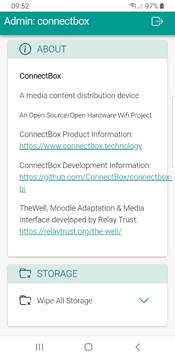
About:
This section gives you an overview of the history of the firmware/software that is used by the Connectbox and the organizations who have contributed to make is possible.
Storage:
This final element of the admin menu allows you to immediately erase all content on the unit. It does this first by deleting all files and folders then by moving on to overwrite all content areas with random data patterns to ensure that the data is not recoverable if the device is found or investigated. Note that it takes some time to wipe the data in this way. Also note that you will have fully erased all content from your device. To make it usable again you will have to reload the content packages form the Cloud based host package server or form a USB key. Note: if you are using a USB key for your storage space it will erase the /content folder of this key only. If you are using the on board uSD for storage it will erase the on board media storage only.
13. Enabling SSH access for the device:
There is a way to enable you to SSH into the unit after booting up. This is accomplished by plugging in a USB Flash drive with the following structure in place:
root directory ─.connectbox
└── enable-ssh
Note that the directory is (dot) connectbox with a single file enable-ssh that can be blank or empty.
As soon as this is plugged in to the device it will activate the SSH for the root account. If the USB is pulled out SSH will remain operational until the unit is rebooted or shutdown.
14. Upgrading the firmware with interim patches:
It is possible that interim patches will be released for V2 firmware. These patches are applied in the following manner. Using a clean USB flash drive load the patch code into the following directory structure:
root directory ─ .connectbox
├──upgrade
├── Prerun
├── Postrun
├── update
├── CM4version
└── upgrade.py
When this USB flash drive is inserted, the operating system will detect the .connectob folder then look for the upgrade folder and look for the upgrade.py file within the upgrade folder. If it exists, it will then copy the upgrade code/directories to the internal memory and execute the upgrade. If successful it will then will create an Upgrade xxxzxxxx.log file in the uSD directory /usr/local/connectbox/. Additionally, it will delete the folders and upgrade.py file from the /tmp directory. If the upgrade failes, you will get a message on the display indicating failure and an error code. Contact [help@connectbox.org](mailto:help@connectbox.org) for additional assistance. If the upgrade was successful, you will receive a notice of success on the screen and you can remove and reformat the USB flash drive you used.
15. Enabling Custom Web Interface:
By default, your ConnectBox is configured to run using what we call the Enhanced User Interface . In this mode, the content that is displayed in your end user s browser is either a single piece of media which has a thumbnail generated for it (such as a frame from a video) or an Icon indicating the type of media it is along with a name. If you need to host a unique website for your application, please refer to Creating a unique website configuration document. This document explains how to create a unique website or to install other web tools such as WordPress.
16. Enabling Custom WordPress site:
If you desire to create your own web interface using the NGINX server, then please refer to the iConfiguring a ConnectBox for WordPress document.
17. Linking your Connectbox to Control Host:
The connectbox can be run independently in the field or it can be connected periodically to a control host system for an organization or for reporting of statistical information for media being used from another vendor. The host management system allows for content packages to be prepared for download to specific Connectboxe’s. It also allows for return uploading of statistical information from the connectbox in the field. This is done by connecting the connectbox to the internet periodically either through an access point with internet access, or through a mobile phone with a data plan tethered to the connectbox. (Note an access point can simply be a local sharing of your mobile data plan as a hotspot for the connectbox to connect to.)
The following diagram outlines the general approach for remote Connectboxes being integrated into the Control Host:
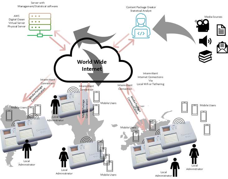
Here media is prepared by the content package creator through the package manager interface of the Control Host system. These packages are then queued for download to the individual Connectboxe s based on unique ID of the box and location/local administrator. When the local connectbox has an internet connection either through an Access Point (AP) or by the local administrator connecting it to one, the media package will be downloaded and installed. Simultaneously it will have its media usage statistics sent to the Control Host system. The Content package creator/or Statistical analyst can then aggregate the information of media usage across units to provide reporting to media vendors that created the content. There are specific role responsibilities in this model.
- 1) Local Administrator, their job is to secure the unit, manage the units capabilities locally, connect it periodically to the internet for retrieval of new content as well as reporting of content usage.
- 2) The Media content creator job is to prepare the packages of media that each unique unit needs as well as to oversee the ensuring of periodic reporting in of the individual boxes from the field through the return of data from the units.
- 3) The Statistician who s job it is to aggregate the statistical information from the Host Controller system and report back to the media providers and internally to the organization.
- 4) The System Administrators job is to setup and mange the Control Host System. This is done either virtually on an Amazon Web Server or other hosting provider, or locally on physical hardware. The are to ensure the ongoing maintenance and patching of software to ensure security of the system.
To facilitate the deployment of the Connectboxe’s for an organization, we have prepared the Host Controller software system installation packages for AWS servers as well as other providers like Digital Ocean through Ansible script files. This will create the structure on the server and provision it. Additional DNS records management may be needed to ensure that the ConnectBox s and system users have easy access to this control system.
Please refer to the documentation on setup and configuration of the control system as well as management and use of the content creator and statistical reporting sides. This will also then provide the information needed in setting up the individual Connectboxe’s.
18: Features:
The Connectbox can be ordered in four models:
Non-Battery Version with power module only Model S V6, Model S V7
Model S version is smaller due to the lack of the battery:
73mm L x 80mm W x 28mm H
99 g Weight
Battery Version with 6,400 mAh battery Model P V6, Model P V7
Model P version is larger and a bit heavier due to the battery:
109mm L x 80mm W x 28mm H
208 g Weight
Both of the A and B versions can be ordered with two accessories:
Accessory 1:
Metal tie wrap to attach the Connectbox to another object/anchor to keep it from being
removed. Once attached the only way to detach it is to cut the metal tie-wrap.
Accessory 2:
Miro-SD card cover that can be inserted inside of the unit to keep the micro-SD card from
being removed without opening the case. This accessory can be retrofitted into existing
Connectbox version 6 units or later. But is best if pre-ordered with the unit.
This is an open source project and we appreciate your feedback and suggestions. Please visit: http://feedback.connectbox.technology/ and leave your comments. Anything posted here will automatically go directly to the developers for consideration.
ConnectBox Homepage: https://connectbox.technology/wp/
ConnectBox Development Source Code: https://github.com/ConnectBox](https://github.com/ConnectBox
ConnectBox Discussion Forum: https://groups.google.com/forum/#!forum/connectbox](https://groups.google.com/forum/#!forum/connectbox